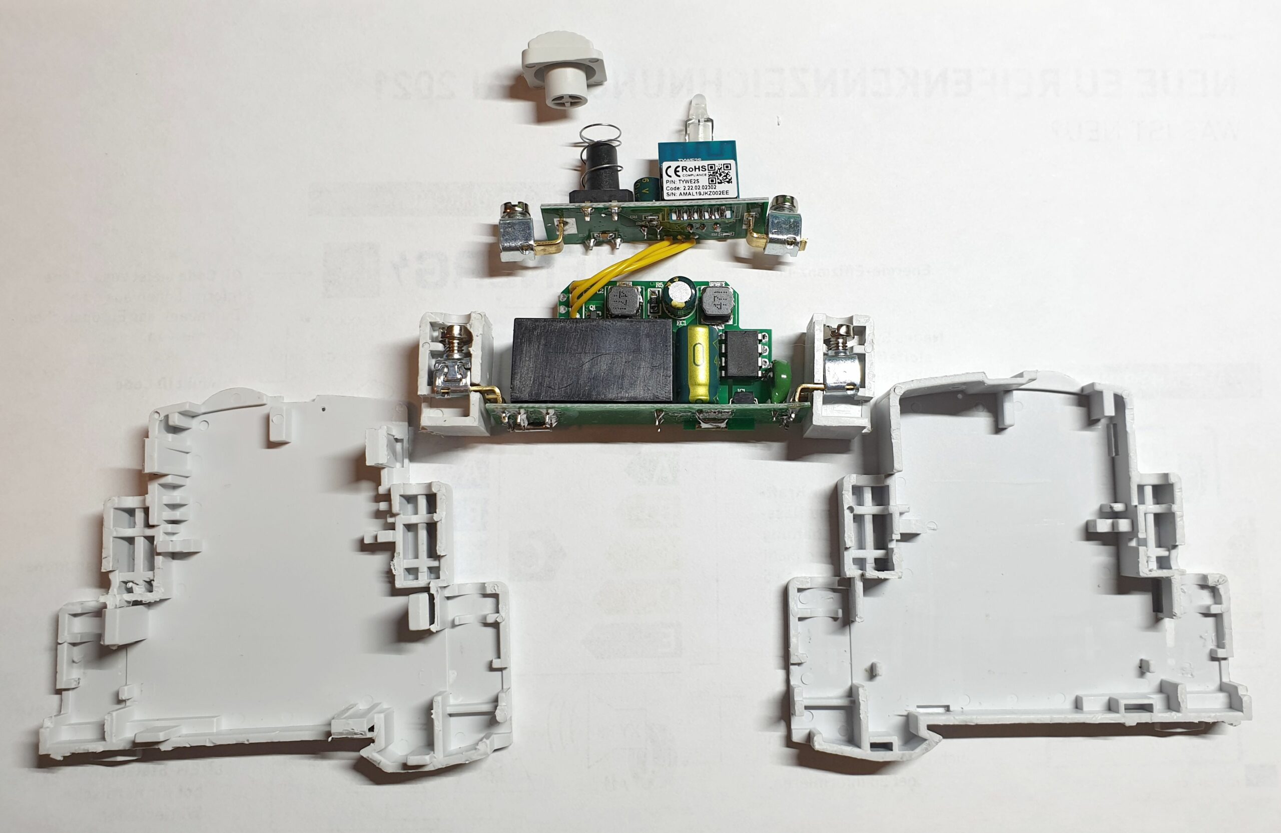
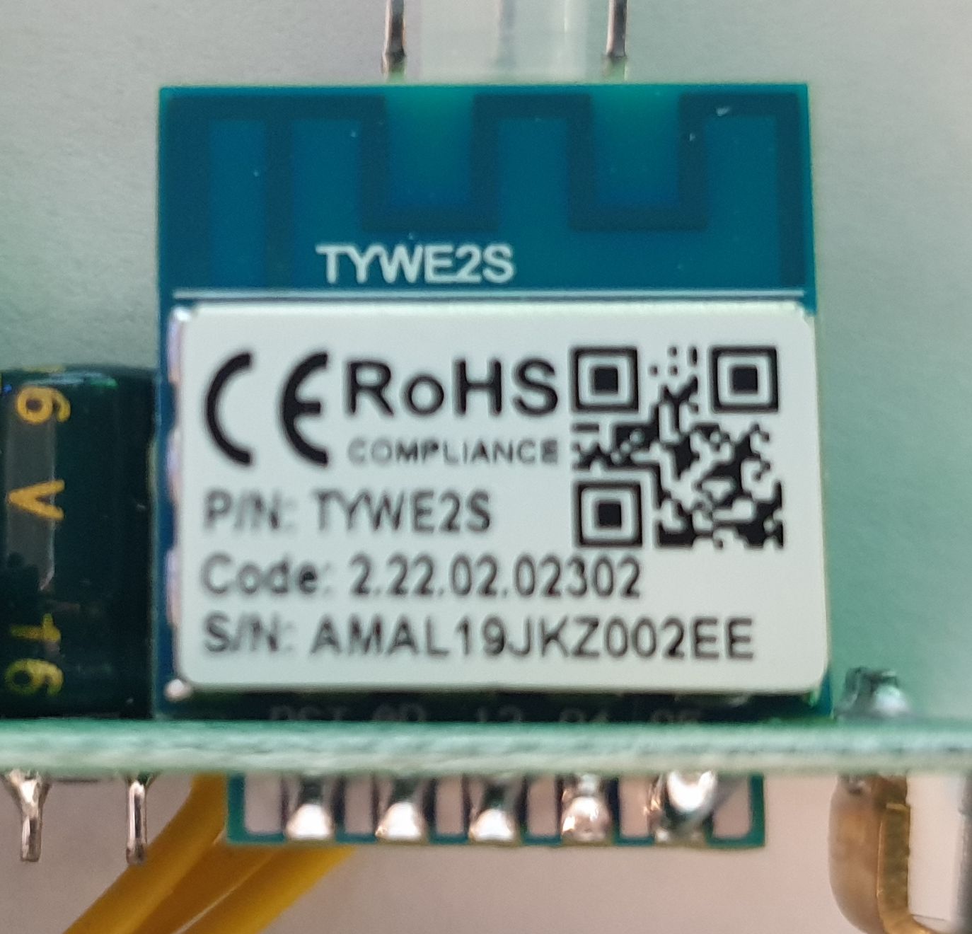
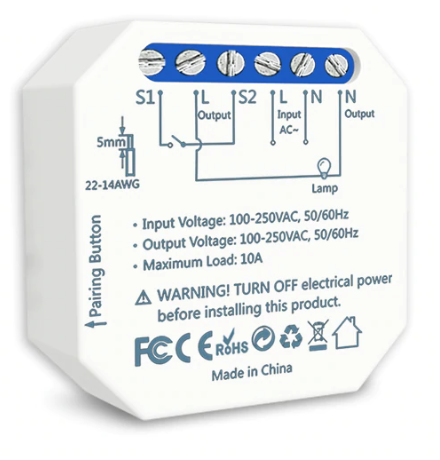
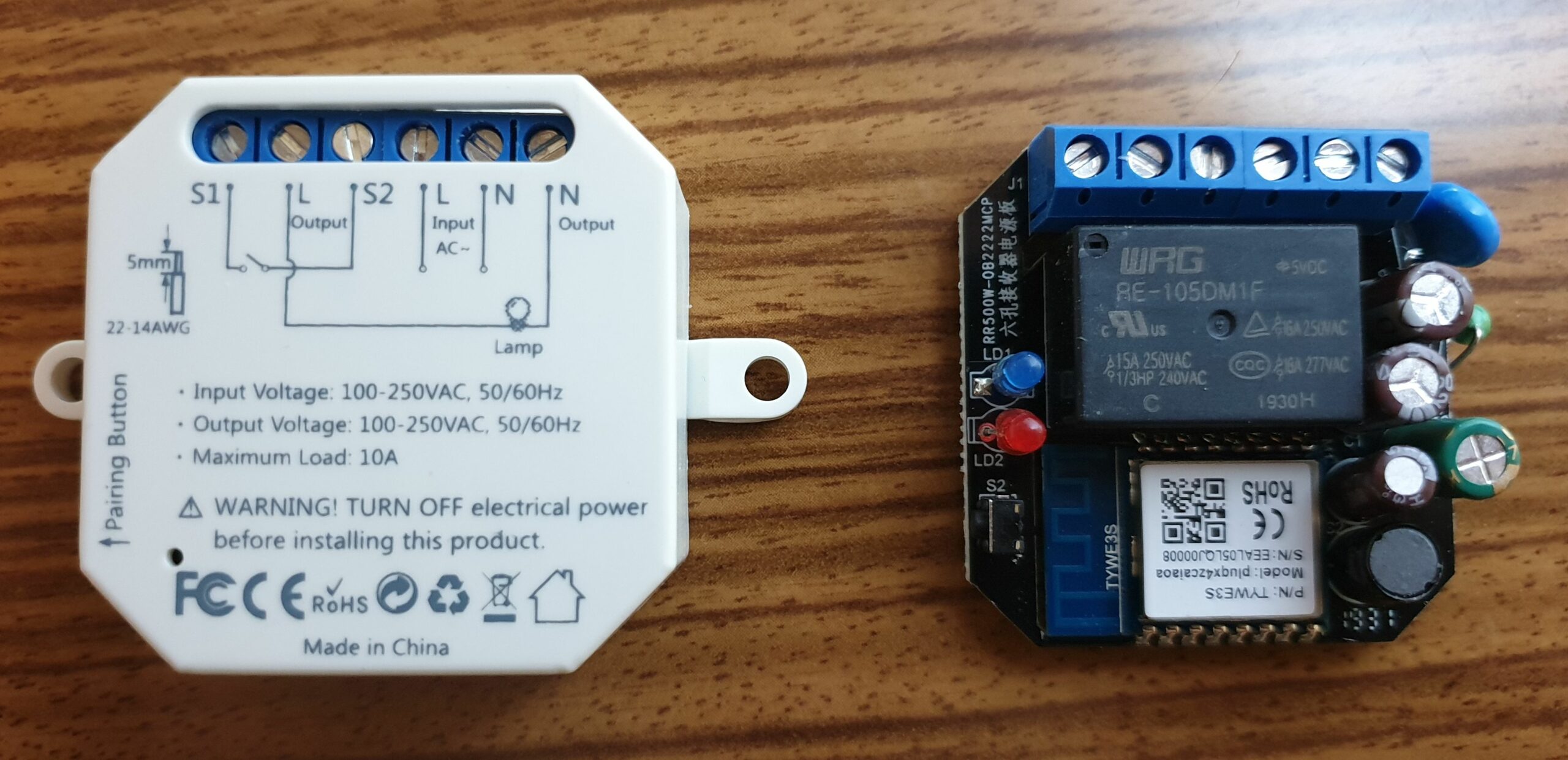
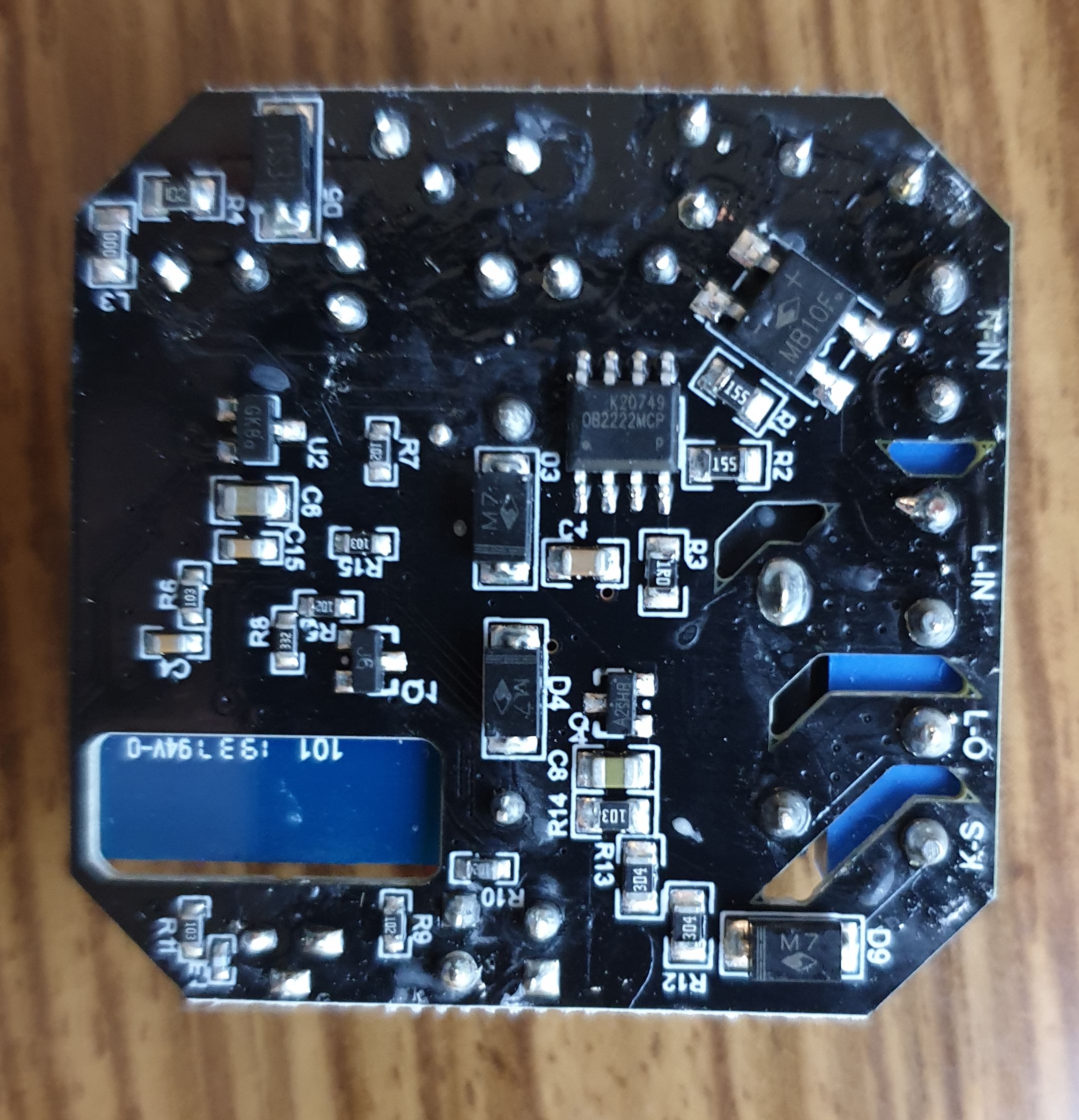
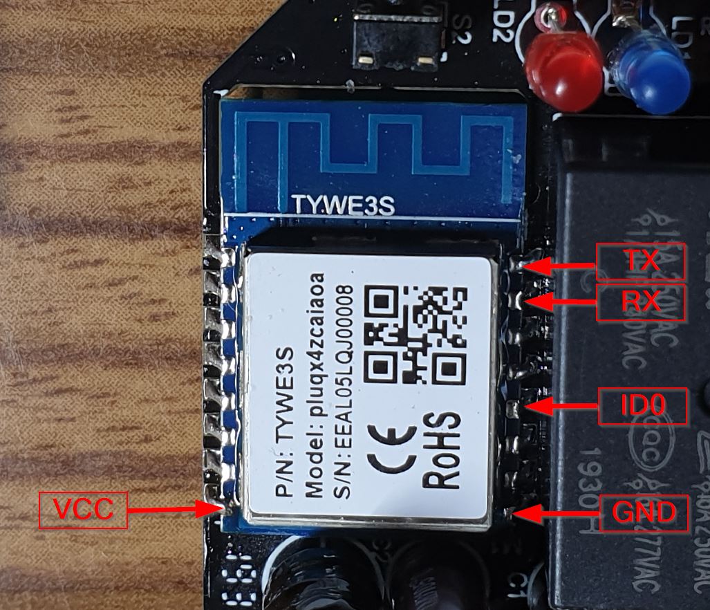
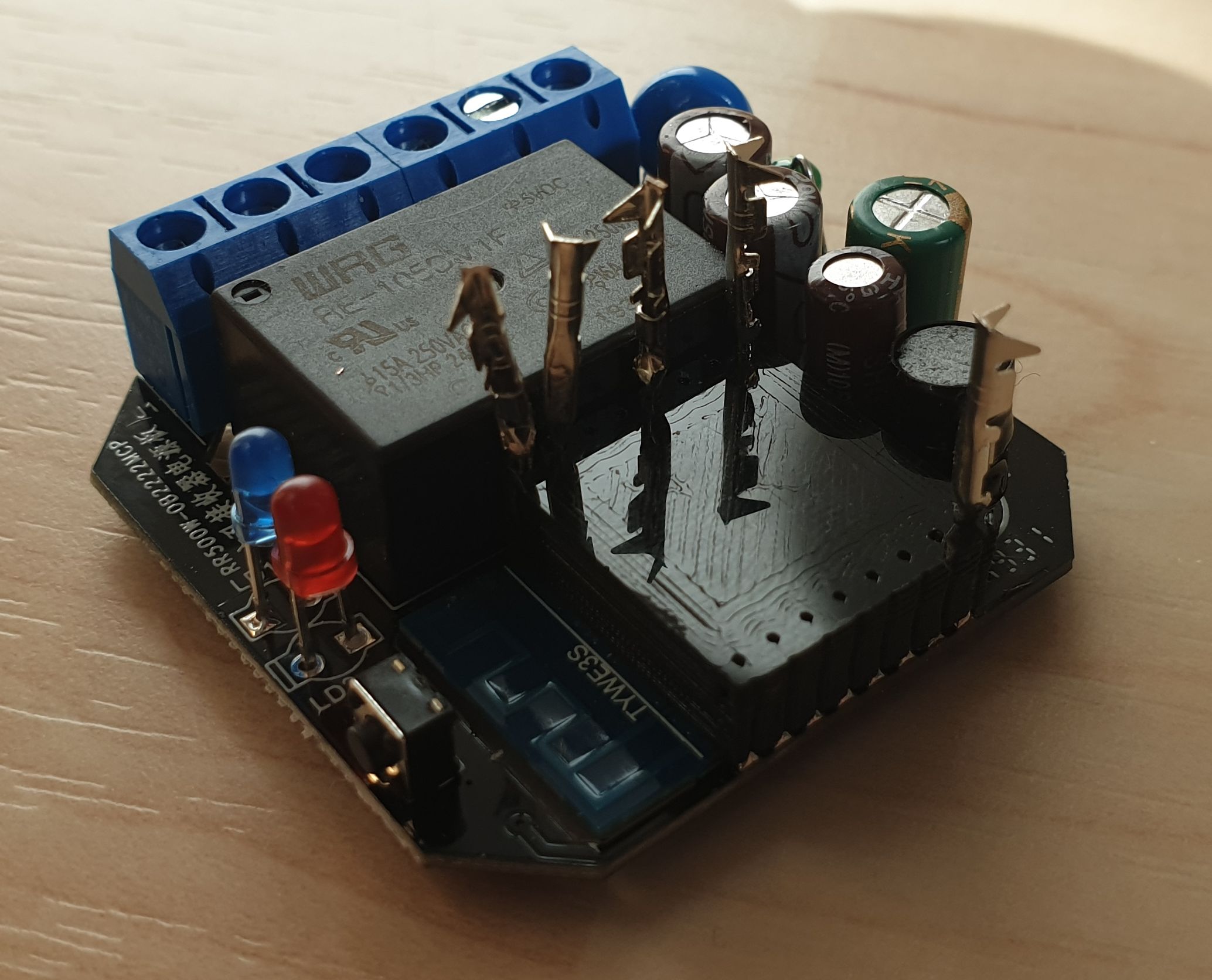
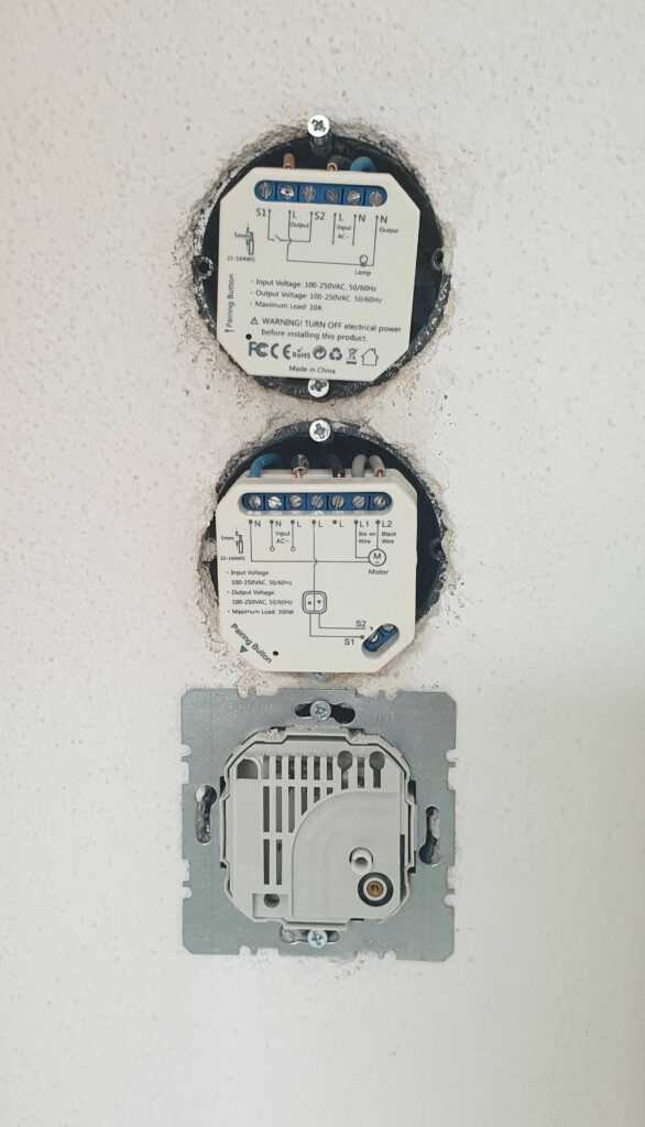
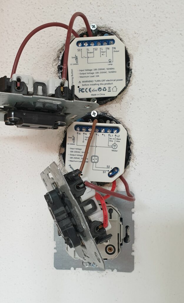
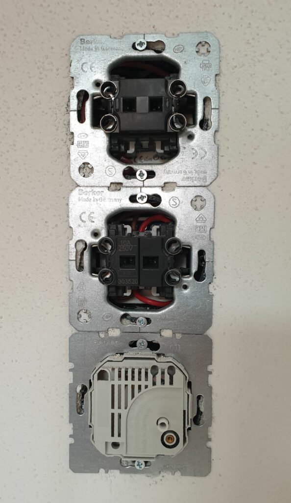
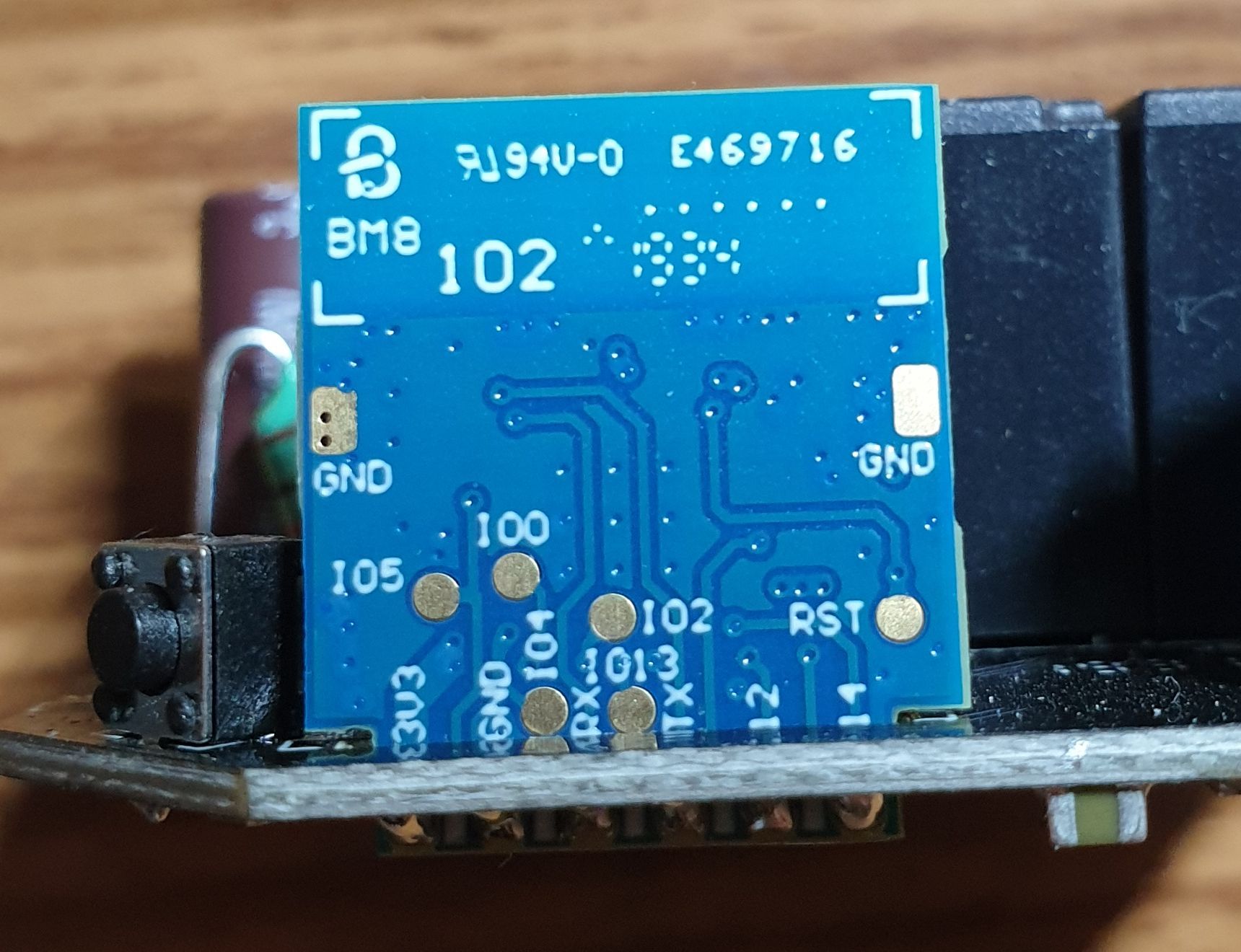
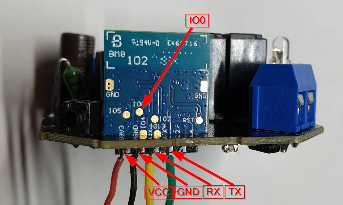
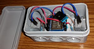
HARDWARE
Hardware and setup for flashing is described in the following article:
FIRMWARE FEATURES
- Control over MQTT broker.
- State report contains information on switch state – server gets informed if any of switches is actually pressed by user or not. Means server gets info whether state was changed due to physical action, or due to command via MQTT.
- On ESP a Light-Sleep mode is activated, which allows to reduce consumption from 0.8w to 0.5w, without any side-effects on switches reaction.
- Might be configured with some settings.
- It’s possible to adjust configuration without necessaty to uninstall and reflash module.
- It’s possible to update firmware over-the-air (OTA) – it’s not necessary to unplug, disassemble and solder module to get updates.
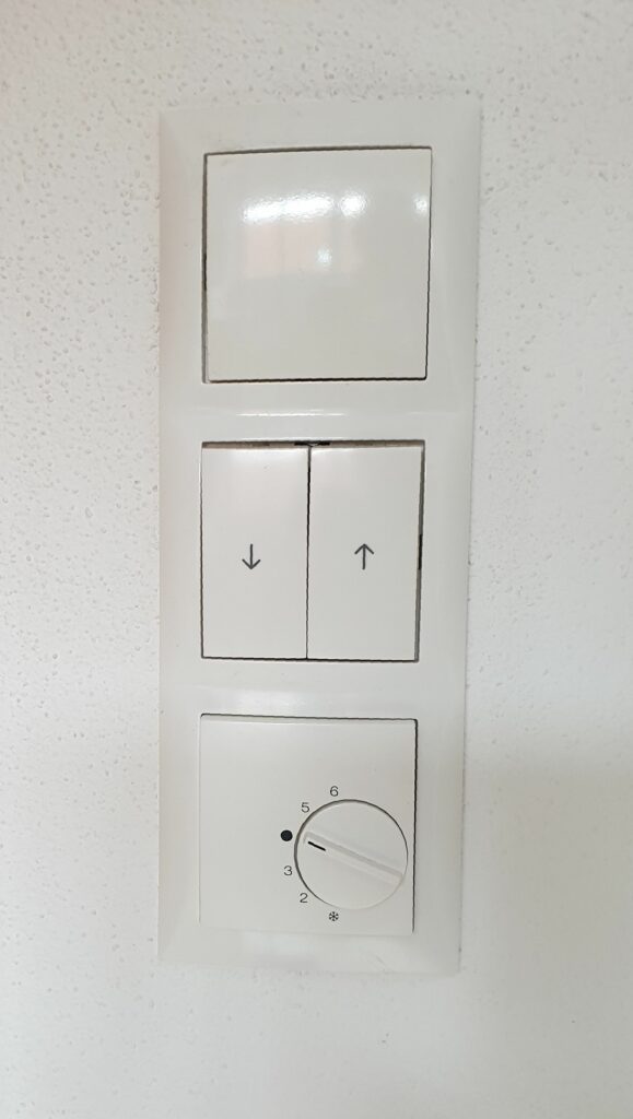
WORKING MODES
- Red LED blinks slowly – module is in configuration mode. At this moment open WiFi hotspot “Dozy-xxxxx” is enabled. Configuration page can be accessed at IP 192.168.4.1. Or, if network connection isn’t lost, it’s possible to access configuration page at local IP address. After 5 minutes timeout it quits configuration mode.
- Red LED blincs quickly – module is in OTA flashing mode. The OTA service is running and waits a connection from Arduino studio over network port. After 5 minutes timeout module leaves OTA mode and gets rebooted.
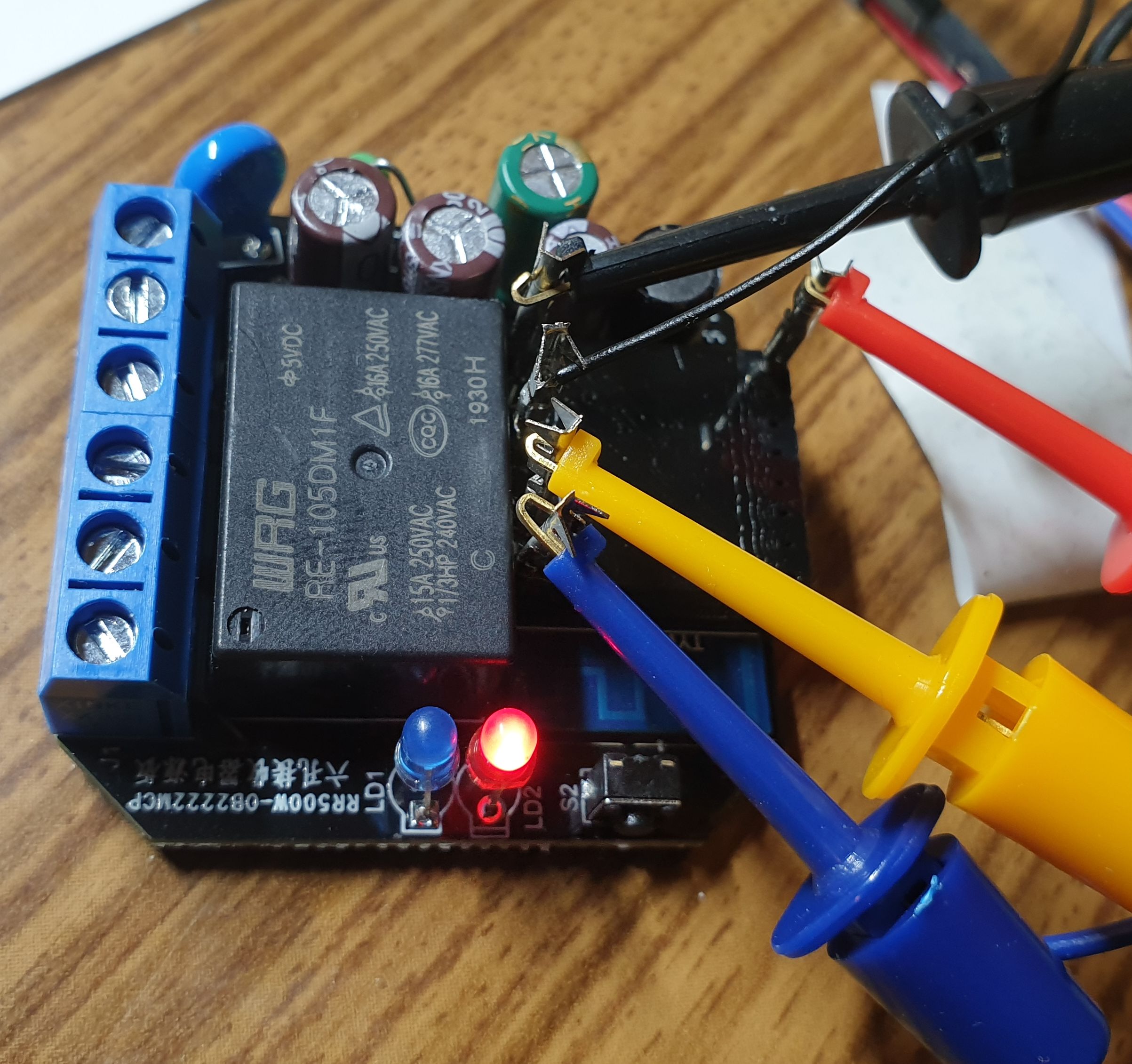
- Green LED reflects relay’s state: close or open.
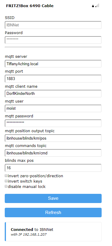
CONFIGURATION
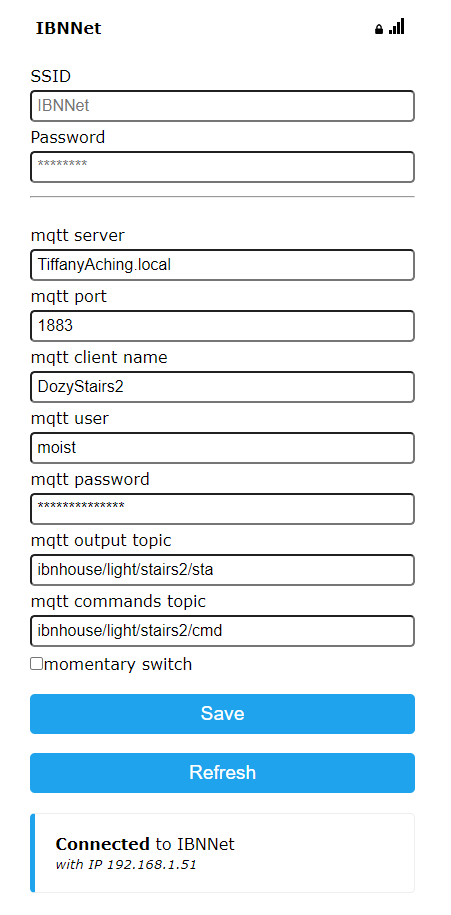
- SSID, password – WiFi network connection.
- mqtt server, port, client name, user, password – connection to MQTT broker. Note: Client name must be unique! This name also used for Access Point name, and as a Hostname.
- mqtt output topic – topic for output of current relay state. Values 0, 1 correspond to off and on accordingly. When status update is triggered by user action, the value is also suffixed with a dot.
Examples:
‘0.’ – relay is open, button was pressed by user.
‘1’ – relay is closed, button wasn’t pressed by user.
‘1.’ – relay is closed, button was pressed by user. - mqtt commands topic – topic for commands input.
- momentary switch – when disabled – each manual button state change triggers relay state change.
When enabled – triggers relay state change on button press action only.
CONTROL COMMANDS
1– turn light on (close relay).0– turn light off (open relay).set– enter configuration mode. Analogue quick button press more than 5 times.-
ota– enter OTA mode. -
rst– reboot module.
Sources
See GitHub: https://github.com/ai91/dozy/
Note that it uses development branch of WiFiManager. This branch can start wifi-manager in non-blocking mode. In this mode the module remains fully operable and can be controlled with manual switches (for example if network wasn’t configured properly). Master-branch still doesn’t support this mode.
MORE
There is also a configuration example of MajorDoMo server (unfortunately in Russian only):