Dozy – multiway switch on DIN rail – firmware

HARDWARE

Hardware and setup for flashing is described in the following article:

FIRMWARE FEATURES

  • Control over MQTT broker.
  • State report contains information on switch state – server gets informed if any of switches is actually pressed by user or not. Means server gets info whether state was changed due to physical action, or due to command via MQTT.
  • On ESP a Light-Sleep mode is activated, which allows to reduce consumption from 0.8w to 0.5w, without any side-effects on switches reaction.
  • Might be configured with some settings.
  • It’s possible to adjust configuration without necessaty to uninstall and reflash module.
  • It’s possible to update firmware over-the-air (OTA) – it’s not necessary to unplug, disassemble and solder module to get updates.

WORKING MODES

  • Red LED blinks slowly – module is in configuration mode. At this moment open WiFi hotspot “Dozy-xxxxx” is enabled. Configuration page can be accessed at IP 192.168.4.1. Or, if network connection isn’t lost, it’s possible to access configuration page at local IP address. After 5 minutes timeout it quits configuration mode.
  • Red LED blincs quickly – module is in OTA flashing mode. The OTA service is running and waits a connection from Arduino studio over network port. After 5 minutes timeout module leaves OTA mode and gets rebooted.
  • Green LED reflects relay’s state: close or open.

CONFIGURATION
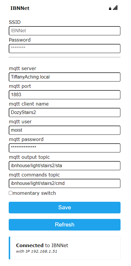
  • SSIDpassword – WiFi network connection.
  • mqtt serverportclient nameuserpassword – connection to MQTT broker. Note: Client name must be unique! This name also used for Access Point name, and as a Hostname.
  • mqtt output topic – topic for output of current relay state. Values 0, 1 correspond to off and on accordingly. When status update is triggered by user action, the value is also suffixed with a dot.
    Examples:
    ‘0.’ – relay is open, button was pressed by user.
    ‘1’ – relay is closed, button wasn’t pressed by user.
    ‘1.’ – relay is closed, button was pressed by user.
  • mqtt commands topic – topic for commands input.
  • momentary switch – when disabled – each manual button state change triggers relay state change.
    When enabled – triggers relay state change on button press action only.

CONTROL COMMANDS

  • 1 – turn light on (close relay).
  • 0 – turn light off (open relay).
  • set – enter configuration mode. Analogue quick button press more than 5 times.
  • ota – enter OTA mode.
  • rst – reboot module.

Sources

See GitHub: https://github.com/ai91/dozy/

Note that it uses development branch of WiFiManager. This branch can start wifi-manager in non-blocking mode. In this mode the module remains fully operable and can be controlled with manual switches (for example if network wasn’t configured properly). Master-branch still doesn’t support this mode.

MORE

There is also a configuration example of MajorDoMo server (unfortunately in Russian only):

Dozy – multiway switch on DIN rail hardware

Module is based on Chinese “Smart Timer Staircase Din Rail Time Switch” ATMS1601.

Module’s main controller is a TYWE2S, based on ESP8285.

Original firmware operates through tuya-cloud. Like Dorfl/Detrius and Dee, we’ll be flashing custom firmware.

To flash firmware we need an RS232 interface with 3.3v. I was using FTDI.

We need 5 connection points.

TYWE2SFTDI
VCCVCC
GNDGND
RXTX
TXRX
IO0GND

Connection is pretty simple. Don’t forget to set 3.3v on FTDI! It’s necessary to pull IO0 to GND to boot in flash-mode.

Following GPIO’s are used in the module:

GPIOModeDescription
4outgreen LED (1 – off, 0 – on)
5outred LED (1 – off, 0 – on)
12outrelay (1 – open, 0 – closed)
13inbutton/switch (0 – released, 1 – pressed)

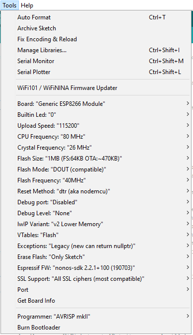
Set following parameters in the Arduino Studio:
Generic ESP8285 Module, CPU 80MHz, Crystal 26MHz, Flash Size 1MB

Firmware:

Dee – single channel light switch – firmware

HARDWARE

Hardware and setup for flashing is described in the following article:

FIRMWARE FEATURES

  • Control over MQTT broker.
  • State-report contains additional information of switches state – server gets informed if switch is actually pressed by user or not.
  • On ESP a Light-Sleep mode is activated, which allows to reduce consumption from 0.8w to 0.5w, without any side-effects on switches reaction.
  • Might be configured with some settings. It’s possible to invert manual switches.
  • It’s possible to adjust configuration without necessaty to uninstall and reflash module.

WORKING MODES

  • Red LED is on – module is powered on and firmware successfully initialized.
  • Blue LED blinks – module in configuration mode. At this moment open WiFi hotspot “Dee-xxxxx” is enabled. Configuration page can be accessed at IP 192.168.4.1. Or, if network connection isn’t lost, it’s possible to access configuration page at local IP address.
  • Blue LED is on – module in fully operating mode.

OPERATION CONTROLS

  • Has two operating modes: each manual switch state change triggers relay state change; or manual switch turns on/off light only if it moved to appropriate position.
  • Enter configuration mode: quickly press some switch 5 or more times.

CONFIGURATION

  • SSID, password – WiFi network connection.
  • mqtt server, port, client name, user, password – connection to MQTT broker. Note: Client name must be unique! This name also used for Access Point name, and as a Hostname.
  • mqtt output topic – topic for output of relay 1 current state. Value is 0/1 for off/on states. Additionally contains a manual switch state by providing a dot in the end.
    Examples:
    ‘0.’ – relay is off, switch is pressed.
    ‘1’ – relay is on, switch released.
    ‘1.’ – relay is on, switch pressed.
  • mqtt commands topic – topic for relay commands input.
  • respect switch stateswhen disabled, each manual switch state change triggers relay state change. When enabled – pressing manual switch, turns on relay. If relay already was on, then does nothing.
  • invert switch keys – inverts manual switch logic (also makes effect on mqtt output of ‘.’ symbol).

CONTROL COMMANDS

  • 1 – turn on light (closes relay).
  • 0 – turn off light (opens relay).
  • set – enter configuration mode. Analogue pressing ‘Pairing button’ or quick switch on-off more than 5 times.

SOURCES

See GitHub: https://github.com/ai91/dee

Note that it uses development branch of WiFiManager. This branch can start wifi-manager in non-blocking mode. In this mode the module remains fully operable and can be controlled with manual switches (for example if network wasn’t configured properly). Master-branch still doesn’t support this mode.

MORE

There is also a configuration example of MajorDoMo server (unfortunately in Russian only):

Detritus – two-channel light switch – firmware

HARDWARE

Hardware and setup for flashing is described in the following article:

FIRMWARE FEATURES

  • Control over MQTT broker.
  • State-report contains additional information of switches state – server gets informed if any of switches is actually pressed by user or not.
  • On ESP a Light-Sleep mode is activated, which allows to reduce consumption from 0.8w to 0.5w, without any side-effects on switches reaction.
  • Might be configured with some settings. It’s possible to swap switches and relays.
  • It’s possible to adjust configuration without necessaty to uninstall and reflash module.

WORKING MODES

  • LED blinks – module is in configuration mode. At this moment open WiFi hotspot “Detritus-xxxxx” is enabled. Configuration page can be accessed at IP 192.168.4.1. Or, if network connection isn’t lost, it’s possible to access configuration page at local IP address.
  • LED is on – module is in fully operating mode.

OPERATION CONTROLS

  • Has two operating modes: each manual switch state change triggers relay state change; or manual switch turn on/off light only if it moved to appropriate position.
  • Enter configuration mode: quickly press some switch 5 or more times.

CONFIGURATION

  • SSID, password – WiFi network connection.
  • mqtt server, port, client name, user, password – connection to MQTT broker. Note: Client name must be unique! This name also used for Access Point name, and as a Hostname.
  • mqtt output topic 1 – topic for output of relay 1 current state. Value is 0/1 for off/on states. Additionally contains a manual switch state by providing a dot in the end.
    Examples:
    ‘0.’ – relay is off, appropriate switch is pressed.
    ‘1’ – relay is on, appropriate switch released.
    ‘1.’ – relay is on, appropriate switch pressed.
  • mqtt commands 1 topic – topic for relay L1 commands input.
  • mqtt output topic 2 – topic for output of relay L2 current state.
  • mqtt commands 2 topic – topic for relay L2 commands input.
  • swap relays – when checked, swaps manual switches for relays (S1 controls L2, S2 controls L1).
  • respect switch states – when disabled, each manual switch state change triggers relay state change. When enabled – pressing manual switch, turns on relay. If relay already was on, then does nothing.
  • invert switch keys – inverts manual switch logic (also makes effect on mqtt output of ‘.’ symbol).

CONTROL COMMANDS

  • 1 – turn on appropriate relay (closes).
  • 0 – turn off appropriate relay (opens).
  • set – enter configuration mode. Analogue pressing ‘Pairing button’ or quick switch on-off more than 5 times.

Sources

See GitHub: https://github.com/ai91/detritus

Note that it uses development branch of WiFiManager. This branch can start wifi-manager in non-blocking mode. In this mode the module remains fully operable and can be controlled with manual switches (for example if network wasn’t configured properly). Master-branch still doesn’t support this mode.

More

There is also a configuration example of MajorDoMo server (unfortunately in Russian only):

Dorfl – blinds control – firmware

Hardware

Hardware and setup for flashing is described in the following article:

Firmware features

  • Control over MQTT broker.
  • Approximately knows state/position of blinds. Fully opened blinds – is zero-position. Once close-switch is pressed for one second – it’s position 1. Every time switch button is pressed, the module calculates time of operation and updates position state (and pushes value to MQTT queue). Means server-side gets info about current position of blinds (fully opened, half-closed, or fully-closed), and can send more precise commands to control blinds. It’s posible to send a command for relative positioning (like “close down-relay for 3 seconds”), or for absolute positioning (“move blinds to the position of 6 seconds from fully-opened”. In this case module will automatically adjust position from current state, without necessity to fully open in advance – it simply makes minimum-required movement to get into desired state). Due to fact that position is calculated by module itself, rather than server, network communication is not a problem at all (unstable network, laggy MQTT broker, etc).
  • Also state-report contains additional information of switches state – server gets informed if any of switches is actually pressed by user or not.
  • On ESP a Light-Sleep mode is activated, which allows to reduce consumption from 0.8w to 0.5w, without any side-effects on switches reaction.
  • Might be configured with some settings. It’s possible to invert zero-position, swap switches and relays.
  • It’s possible to adjust configuration without necessaty to uninstall and reflash module.

Working modes

  • LED blinks – module is in configuration mode. At this moment open WiFi hotspot “Dorfl-xxxxx” is enabled. Configuration page can be accessed at IP 192.168.4.1. Or, if network connection isn’t lost, it’s possible to access configuration page at local IP address.
  • LED is on – module is in fully operating mode.

Operation controls

  • Lock remote control in fully opened/closed state: if keep manual switch pressed, the remote control is blocked.
  • Lock remote control at any position: turn switches off, then quickly press switch on, press off, then again press on and keep in this state (off->on-off-on). At this moment remote control gets blocked and relay remains in open state.
  • Enter configuration mode: quickly press some switch 5 or more times.
  • Even if some manual switch remains pressed forever, relay gets automatically opened after MaxPos seconds.

Configuration

  • SSID, password – WiFi network connection.
  • mqtt server, port, client name, user, password – connection to MQTT broker. Note: Client name must be unique! This name also used for Access Point name, and as a Hostname.
  • mqtt position output topic – topic for output of current curtain position. Value is always in range [0, MaxPos]. Value is an integer with amount of seconds from completely open blinds. Usually it’s written on relay open (after blinds movement is done), but when triggered with manual switch – also on trigger time. When triggered with manual switch, it also contains a dot in the end.
    Examples:
    ‘0’ – blinds fully open.
    ’30’ – blinds at position 30 (means was closing at least for 30 seconds. But can be more, if MaxPos = 30)
    ’30.’ – position 30 seconds and switch is pushed. (i.e. remote control is blocked).
  • mqtt commands topic – topic for commands input.
  • blinds max pos – maximum blinds position (MaxPos).
  • invert zero-position – inverts relays for open/close direction. By default L1 is for opening, L2 for closing.
  • invert switch keys – inverts manual switch logic. By default S1 is for opening, S2 for closing.
  • disable manual lock – when set, the “Lock at specific position” is disabled. Experimental, to get rid of potential problems when it interferes with normal work.

Control commands

  • mvr<XXX> – move to relative position XXX. XXX can be negative. If XXX negative – it moves curtain UP (closes L1 relay). If positive – DOWN (L2 relay). Absulute value of XXX – is amount of seconds to keep closed relay.
    Examples:
    mvr5 – close relay L2 for 5 seconds (closing curtains)
    mvr-60 – close relay L1 for 60 seconds (opening curtains)
    mvr0 – open both relays. I.e. stop curtains.
    Note: module takes care of conflicts and guaratees only one relay can be closed at a time. I.e. sequental mvr5 mvr-5 won’t burn engine, rather terminates/cancels first command.
  • mva<XXX> – move to absolute position XXX. XXX can be negative or any big number. If XXX is out of range of curtains [0, MaxPos], then after XXX seconds it will be set to 0 or MaxPos.
    Examples:
    mva0 – fully open curtains.
    mva5 – move curtains from current position to position 5 seconds from fully-open position. If current position is 3, then it will keep L2 closed for 2 seconds. If current position is 9, then will keep L1 closed for 4 seconds.
    mva60 – fully close curtains. Will be keeping L2 closed for 60 seconds, then position value will be set to MaxPos.
    mva-60 – fully open curtains. Will be keeping L1 for 60 seconds, then position value will be set to 0.
  • set – enter configuration mode. Analogue pressing ‘Pairing button’ or quick switch on-off more than 5 times.

Sources

See GitHub: https://github.com/ai91/dorfl/

Note that it uses development branch of WiFiManager. This branch can start wifi-manager in non-blocking mode. In this mode the module remains fully operable and can be controlled with manual switches (for example if network wasn’t configured properly). Master-branch still doesn’t support this mode.

More

There is also a configuration example of MajorDoMo server (unfortunately in Russian only):

Dee – single-channel relay module hardware

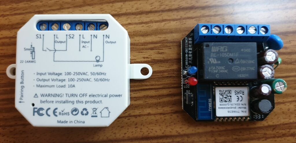
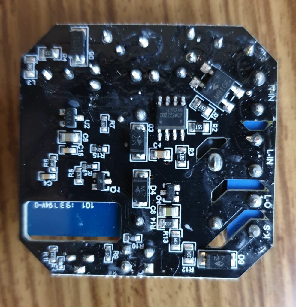
Module is based on WiFi Light Switch module from LoraTap.

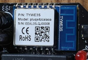
Module’s main controller is a TYWE3S, based on ESP8266.

Original firmware works through tuya could, just like a two-channel module. And exactely same reasons to flash own firmware.

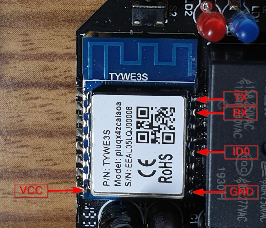
To flash firmware we need an RS232 interface with 3.3v. I was using FTDI.

We need 5 connection points.

TYWE3SFTDI
VCCVCC
GNDGND
RXTX
TXRX
IO0GND

Connection is pretty simple. Don’t forget to set 3.3v on FTDI! It’s necessary to pull IO0 to GND to boot in flash-mode.

Following GPIO’s are used in the module:

GPIO ModeDescription
0outRed LED (1 – on, 0 – off)
4inSwitch (1 – released, 0 – pressed)
12inPairing button (1 – released, 0 – pressed)
13outRelay (0 – open, 1 – close)
16outBlue LED (1 – off, 0 – on)

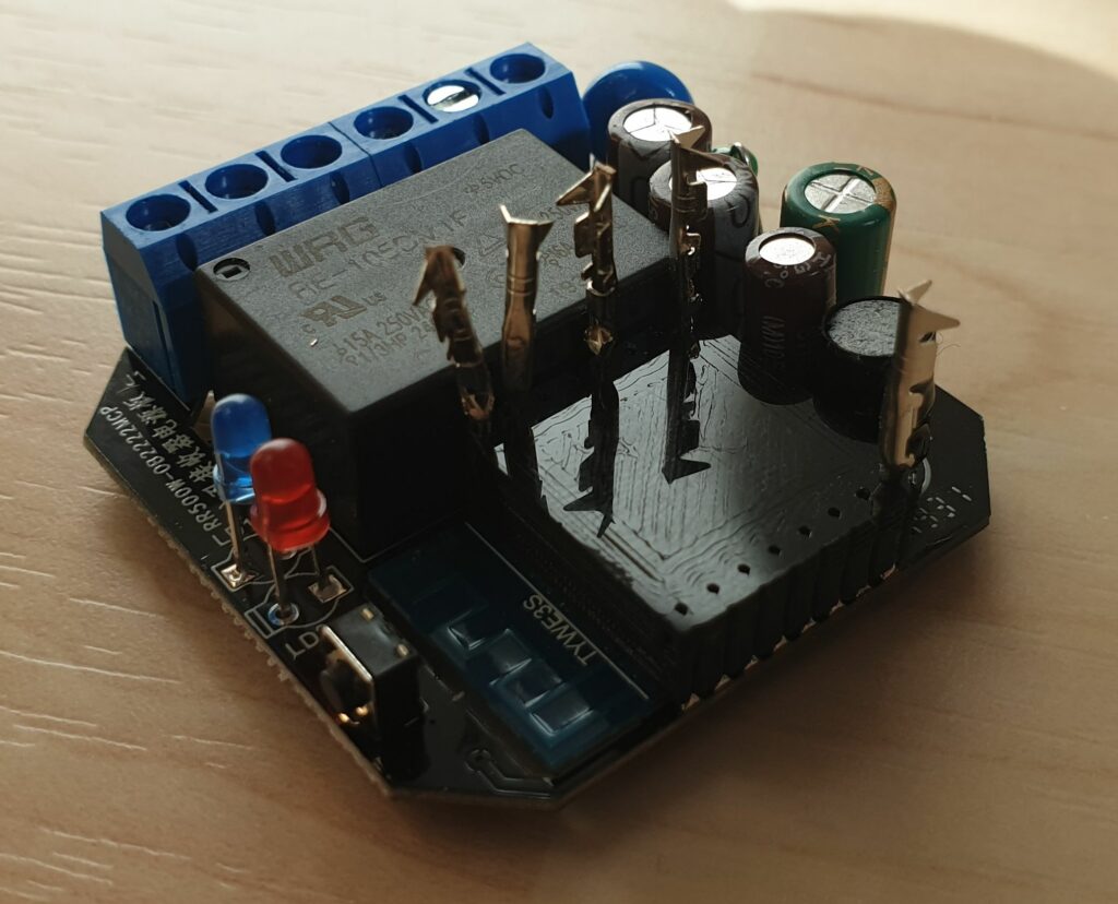
Unfortunately, it’s hardly possible to solder connection-wires without unsoldering TYWE3s module or relay. Therefore I had to design and print a jig. 3D model can be downloaded from Thingiverse.

Set following parameters in the Arduino Studio:
Generic ESP8266 Module, CPU 80MHz, Crystal 26MHz, Flash Size 1MB

Gonna flash Dee firmware:

Dorfl/Detritus – two-channel relay module hardware

Module is based on WiFi Curtain Blind Switch module from LoraTap.

Module’s main controller is a TYWE2S, based on ESP8285.

The great thing about this module, is a full and independent access to relays and GPIO’s. Means with custom firmware it’s possible to turn it into two-channel light switch. Though it’s also possible to make a mistake in relays-control logic – it’s possible to close both relays and burn blinds engine. Therefore we gonna be carefull 🙂

There are two versions of the module in the official store: V1 and V2. I’ve ordered and inspected both of them. I can tell that quality of V2 is higher – soldering is cleaner, cuts are more precise. Though schematics and components are exactely same in both versions. The main difference is in the firmware. V2 supports switch-buttons, while V1 work properly with toggle buttons. But I don’t think it makes a big deal here, as we are going to flash own firmware anyways. In my opinion it doesn’t really makes sense to pay extra for ‘perfect cuts’.

Original firmware isn’t interesting for us. It operates through tuya-cloud. First of all it’s requires permanent internet-connection. Then it might get communication delays. Also it’s not so easy to get control from own software (though community are reverse engeneering). Last but not least, I don’t entrust external access to my private zone. Therefore gonna nail it. 🙂

To flash firmware we need an RS232 interface with 3.3v. I was using FTDI.

We need 5 connection points.

TYWE2SFTDI
VCCVCC
GNDGND
RXTX
TXRX
IO0GND

Connection is pretty simple. Don’t forget to set 3.3v on FTDI! It’s necessary to pull IO0 to GND to boot in flash-mode.

Following GPIO’s are used in the module:

GPIOModeDescription
3outLED (1 – off, 0 – on)
4inswitch S1 (1 – released, 0 – pressed)
5inswitch S2 (1 – released, 0 – pressed)
12outrelay L1 (0 – open, 1 – close)
13inpairing button (1 – released, 0 – pressed)
14outrelay L2 (0 – open, 1 – close)

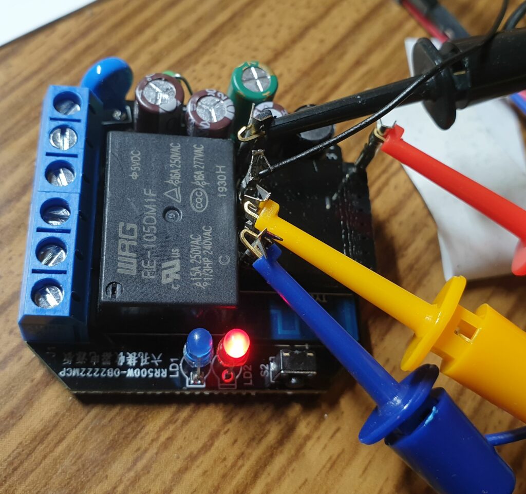
It’s easy to solder connection wires. During development and testing I was using following setup (be carefull with 220v connection! don’t forget to disconnect FTDI from computer. It’s disconnected on the picture)

Set following parameters in the Arduino Studio:
Generic ESP8285 Module, CPU 80MHz, Crystal 26MHz, Flash Size 1MB

Gonna flash two options: